Everything About Stud Welding
Stud welding refers to the joining of weld parts (studs) with flat workpieces by means of a welding arc and the application of a pressing force. The zones are joined in the liquid state of the welding zone. No filler material is used.
In stud welding, an arc is briefly struck between the face of the stud and the work piece; both parts start to melt and are then joined. Depending on the nature of the ignition method, a distinction is made between drawn‐arc stud welding and stud welding with tip ignition. Each method requires suitable power supplies, actuating devices, studs and accessories (e.g. ceramic ferrules). A feature of stud welding is the very short arc burn time (approximately 0,5 ms to 3 000 ms) and the associated high rate of heating and cooling. Normally the diameter of the stud can range up to 10 mm for tip ignition welding, and up to 25 mm for drawn‐arc welding.
What Is Stud Welding?
Drawn Arc Stud Welding
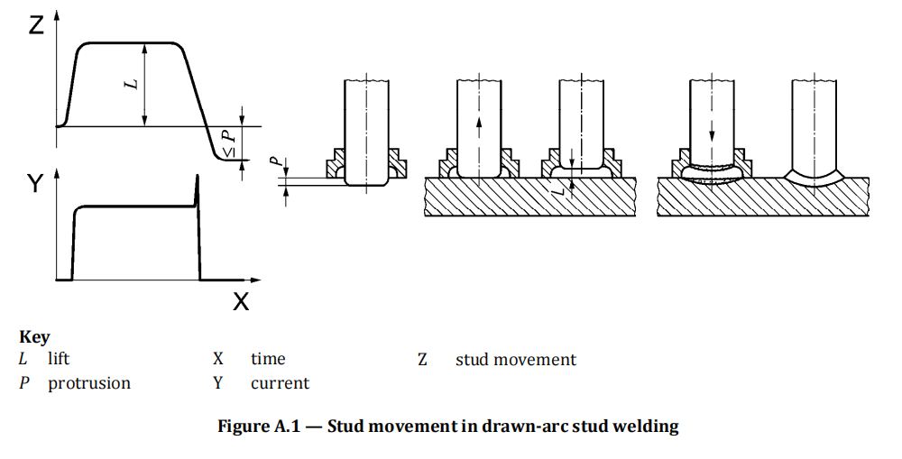
Drawn arc stud welding can be done mechanically or automatically, using welding gun or welding heads. The stud is inserted into the stud holder and ‐ fitted with a ceramic ferrule, if necessary ‐ applied to the work piece. At the beginning of the welding process, the stud is lifted by the mechanism and, normally, first a pilot arc, then the main arc, are struck between the tip of the stud and the work piece. This causes the face of the stud and the parent material to melt. When the welding time has elapsed, the stud is plunged with little force (< 100 N) into the molten
pool, and the current source is switched off. The ceramic ferrule is then removed.
Figure A.1 shows the sequence of events using a ceramic ferrule.
3 Methods of drawn-arc stud-welding processes
a)
Drawn arc stud welding with ceramic ferrule or shielding gas (783).
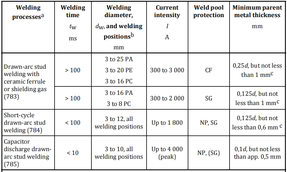
This welding process is generally used in the 3 mm to 25 mm diameter range, with welding times of 100 ms to 3 000 ms. It is usually carried out with a ceramic ferrule or shielding gas, or with both, or in special cases without pool protection. This method is used for the majority of applications. The minimum parent metal thickness is 0,25 d for CF and 0,125 d for SG, but not less than 1 mm.
b)
Short-cycle drawn-arc stud welding (784).
A welding time of ≤ 100 ms is used. This variant is suitable for stud diameters up to 12 mm, but for the range between approximately 8 mm and 12 mm, stud diameter shielding gas should be used to prevent increased pore formation. For aluminium, shielding gas shall be used. The fusion zone is narrow and the thermal input modest, so that studs up to 12 mm diameter can be welded to thin parent metals. For diameters up to 9 mm diameter and with steel, the operation is frequently carried out without protection of the weld pool and calls for studs with an upset flange, as these afford a larger weld area than the plain stud‐shaft diameter and thus reach a higher tensile force than the stud shaft, despite pores in the weld zone. The minimum parent metal thickness is 0,125 d, but not less than 0,6 mm.
c)
Capacitor discharge drawn-arc stud welding (785).
Very short welding time (< 10 ms) can be achieved by using a capacitor discharge power source. The diameter range is 3 mm to 10 mm. The minimum parent metal thickness is 0,1 d, but not less than approximately 0,5 mm. The welding process is similar to the short‐cycle drawn‐arc stud‐welding process, but the peak current can be up to 4 000 A.
Wroking range of the various drawn-arc stud welding process
Capacitor Discharge Stud Welding
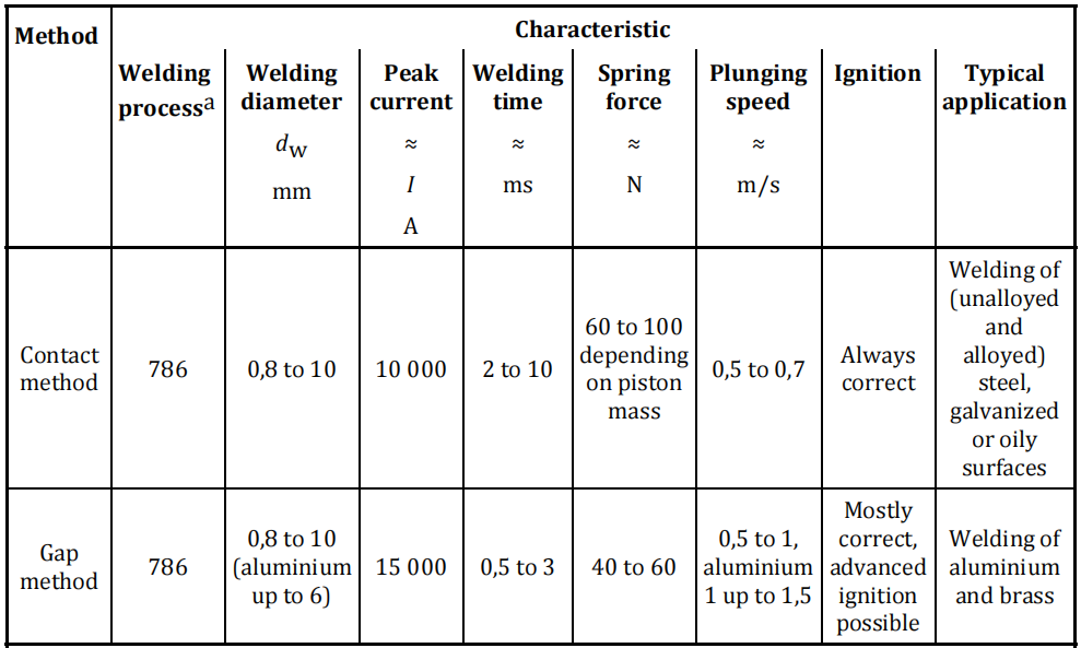
In welding with contact, the stud is inserted into the stud holder of the machine and positioned with its ignition tip directly on the surface of the component. A spring in the welding gun presses the stud against the metal. Once the capacitor power has been switched on, the ignition tip abruptly explodes and vaporizes partially, and the arc is generated. The stud is advanced still further towards the parent metal and finally remains in the solidified melt. The welding time is ≤ 3 ms.
The difference between welding with gap and the technique described above is that, before welding begins, the stud is held at a defined, adjustable distance from the work piece.
When the capacitor bank is switched on, the stud is speeded up towards the surface of the metal, and the welding process continues as described above. A welding time of about 1 ms makes it possible, among other things, to weld aluminium and its alloys without gas shielding. The recommended parent metal thickness should be ≥ 0,1 d but not less than approximately 0,5 mm.
Capacitor discharge stud welding with tip ignition — Main phases of the welding process
Characteristics for capacitor discharge stud welding with tip ignition
About Sinoars
News & Events
Products
Support
Discover


